Published on: 06 January 2026
Positioning your bent part against the backgauge
In order to bend your product on our bending machines, it is essential that we can position your bent part correctly against the backgauge of the machine. In this article, we explain what this is, why it is important, and what this means for the design of your bent parts.
What is the backgauge?
On a bending machine, a punch is pressed straight down into a V-shaped die. Is there a metal plate between them? Then a straight bend line is formed in the plate over the entire length where the punch presses into the V-groove. This creates the bend radius, or in short: a bend.
But can the metal plate move too much? Then there is a risk of the plate shifting, resulting in the bend line being created in the wrong place and deviations occurring.
By placing the plate against a few fixed position points on the bending machine , the risk of movement is minimized and each bend occurs in the same place.
We call these position points the backgauges.
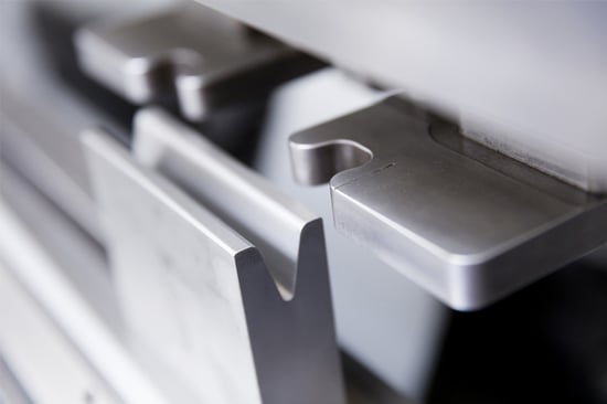
Image 1: The die with two adjustable cylinders behind it.
On bending machines , the backgauge consists of two adjustable arms with cylinders (also called fingers) behind the die. We slide the plate against these and can determine exactly where the bend line will be in relation to the edge of the plate.
Is the bend parallel to the outer contour? Then two position points are sufficient. You can see this in image 2 below; the green dots are the position points.
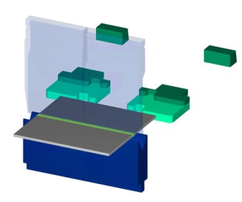

Image 2: A bend parallel to the backgauge.
Although the sheet can slide to the left and right, because the bend line runs parallel to the outer contour, the bend will always be in the right place.
Is the bend not parallel to the outer contour? Then your product will also need to be secured sideways. We do this using the cylinders.
For relatively simple shapes and single bends, you usually do not need to take the backgauge into account. The most important thing is to allow for a minimum stop line of 20 mm.
However, there are situations that require a little more attention. We discuss these below.
When should you, as an engineer, take the backgauge into account?
You must take the backgauge into account in the following situations:
- Tapered shapes
- Round shapes
- Non-right-angled bend
- Bends with holes in the bending zone
1. Tapered shapes
The example below shows when a tapered shape does not have to be a problem. The part is pressed against the stop on the left side with two sides. This prevents the edge from shifting during bending.
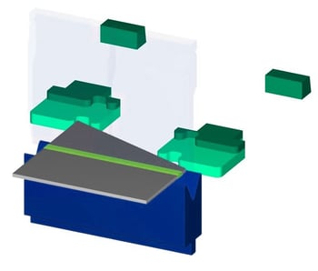

Image 3: Good backgauge for a tapered part.
However, there are also shapes where the point does cause problems. See the example below.
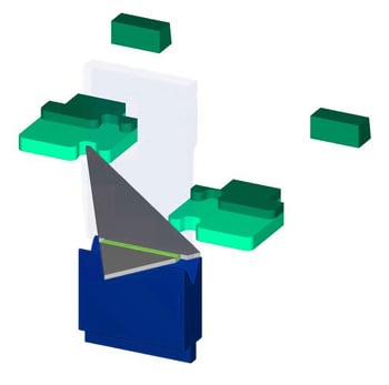

Image 4: Incorrect bakgauge for a tapered part.
The sharp tip of this product does not fit properly into the cylinder. We cannot press it 'firmly' against the backgauge, which makes it impossible to create consistent dimensions.
A possible solution is to give the sharp tip a radius so that it does fit the cylinder.
2. Round shapes
Round shapes do not contain any lines that are parallel or perpendicular to the bend line. The shape keeps moving, which means we cannot clamp it consistently according to the dimensions.
The only way to secure round workpieces is to create a straight gauge line. This is usually done by adding tabs (known as gauging tabs) that create a straight gauge line relative to the bending line. These tabs can be ground off later to restore the round shape.
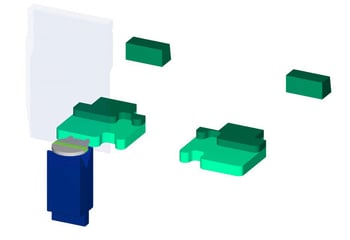

Image 5: Small part with a curve on one backgauge.
The following guidelines apply to the placement of tabs:
- Width of the gauge tab: minimum 5 mm
- Distance between tabs on a single gauge (as shown in image 5): maximum 40 mm
- Distance between tabs on two gauges (as shown in image 6): minimum 200 mm
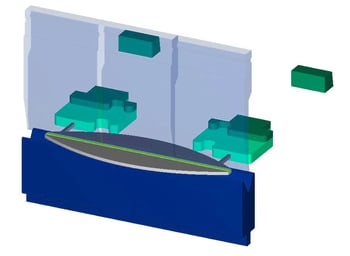

Image 6: Component with a curve on two gauges.
An alternative is to place the tab parallel to the bending direction.
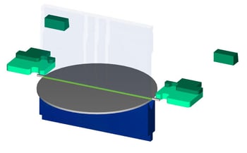

Image 7: Large round part with tabs parallel to the bending line.
This occurs with large, round parts.
Observe the following additional guidelines:
- Width of tabs: minimum 10 mm
- Length of tabs: minimum 40 mm
- Distance between tabs on two gauges: minimum 200 mm
- Positioning of the tabs: 2 mm before the bend line
3. Non-right-angled bend
For edge parts with multiple bends, we occasionally have to press a bended part against the gauge to create another, parallel bend. This is usually not a problem for 90° angles:
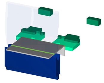

Image 8: Right-angled bend against the gauge.
The right angle provides a sufficiently accurate gauge line for the next bend.
Sharp bends can be pushed against the gauge, but because the outer corner has a radius, this gauge line is not ideal.


Image 9: Sharp bend against the gauge.
The problem is greatest with obtuse bends. Because when we have to strike against an obtuse angle, two risks arise.
Firstly, any deviation from the first bend (see image 10) will be carried over to subsequent bend. After all, we are gauging against this bend.
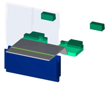
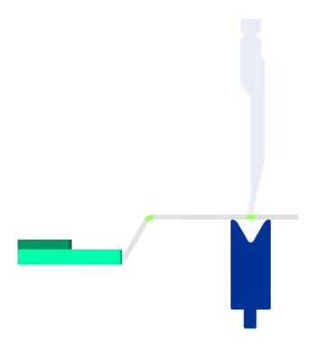
Image 10: End of blunt bend against the gauge.
Secondly, it is difficult to press the non-right-angled bend against the gauge (see image 11). This makes consistent dimensions, for example in series production, much more difficult.
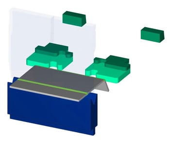

Image 11: Blunt bend against the gauge.
That is why we prefer not to place non-right-angled bends against the gauge.
This makes conical and cylindrical shapes extra challenging (but not impossible) to create. After all, these shapes contain multiple blunt bends to achieve the 'round' shape step by step.
Ideally, we bend each bend in ascending order, as shown below.
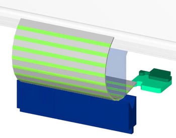
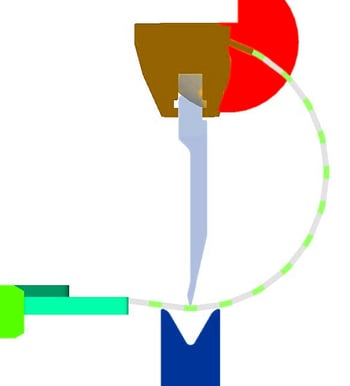
Image 12: Cylindrical shape with ascending bending sequence leads to collision.
However, this is not feasible because the bent flanges collide with the bending machine before all bends have been made.
To prevent collision, we can adjust the bending sequence. We then bend one half step by step first. Then the other half. The middle bend is then done last. You can see this below on the left.
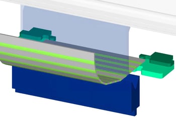
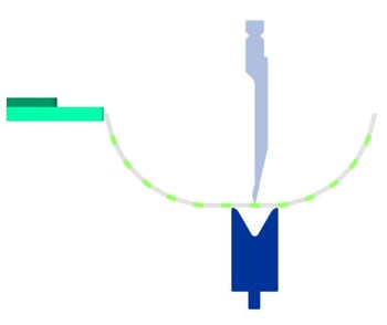
Image 13: Cylindrical shape with adjusted bending sequence leads to non-right-angled bends against the gauge.
But while we solve the collision problem, we create the problem that we have to make a non-right-angled bend against the gauge as the last step (imagef 13, right), resulting in unreliable dimensions.
This brings us to the solution of creating a good gauge for the conical and cylindrical shapes: stop tabs. If you place tabs to the left and right of the center bend line, we use them to press against the gauge and make the final bend with a straight gauge.
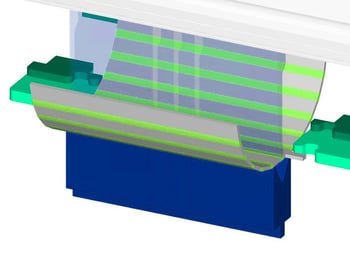
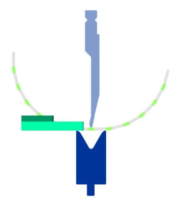
Image 14: Cylindrical shape with adjusted bending sequence and stop tabs leads to correct bends.
Follow these additional guidelines:
- Width of tabs: minimum 10 mm
- Length of tabs: minimum 40 mm
- Distance between tabs on two gauges: minimum 200 mm
- Positioning of the tabs: 2 mm before the bending line
4. Bends with holes in the bend zone
The above may give the impression that right-angled bends can always be positioned correctly against the gauge. Unfortunately, this is not true. Problems can also arise here.
The reason? Holes in the bending zone.
These holes will deform during bending. Although customers often do not find this a problem for the aesthetic end result or fit, they do cause a problem if the bend with deformed holes has to be placed against the gauge in order to make another bend.
Below you can see such a deformation along the bend:
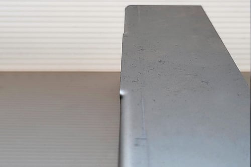
Image 15: Right-angled protruding deformation.
As you can see, the deformation protrudes slightly. If you place this side against the gauge, you will hit the gauge with the bulges and not with the actual flange.
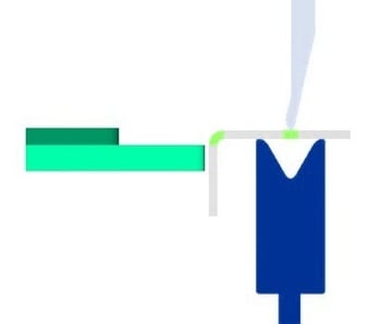
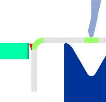
Image 16: Right angle with deformed holes against the gauge.
The result is that your part is actually slightly further away from the stop and your bend line is also further forward.
In Sophia®, you can ignore the warning about holes in the bend zone – at your own risk – and continue with your order. But are these holes located in a bend that must be placed against the gauge? Then the holes will not only affect the aesthetics of your part, but also its dimensions. And that is usually not desirable.
The only solution is to create bend reliefs, i.e., slots that run parallel to the holes in the bend zone.
Questions about positioning against the gauge?
Our software and operators always look for the best possible solution for your parts. But if you take the above into consideration yourself, you will avoid unexpected obstacles and keep your project on track.
Do you have any questions about this topic? Please feel free to contact us.
/csv-import-2600x800.jpg)
/het%20verschil%20tussen%202.5D%2c%203D%20en%20XY%20Lasersnijden.jpg)
/verschillende%20soorten%20collisie%20bij%20kanten.jpg)