


Results by laser cutting with oxygen
Results by laser cutting with nitrogen

Without edge finishing
Without edge finishing
With edge finishing

| Plate thickness up to 2 mm | 1,5 mm | |
| Plate thickness 2,5 to 15 mm | 0,7 x plate thickness | |
| Plate thickness 20 and 25 mm | At least the plate thickness | |
| Plate thickness up to 2 mm | 2 mm | |
| Plate thickness 2,5 | 2.5 mm | |
| Plate thickness 3 mm | 3 mm | |
| Plate thickness 4 mm | 3 mm | |
| Plate thickness 5 mm | 3.5 mm | |
| Plate thickness 6 mm | 4 mm | |
| Plate thickness 8 mm | 5 mm | |
| Plaatdikte 10 mm | 7 mm | |
| ø nitrogen | ø oxygen | |
| Plate thickness 0,8 up to 1 mm | 0,5 mm | |
| Plate thickness 1,25 up to 1,5 mm | 0 ,8 mm | |
| Plate thickness 2 mm | 1 mm | |
| Plate thickness 2,5 mm | 1,25 mm | |
| Plate thickness 3 mm | 1,5 mm | 1,5 mm |
| Plate thickness 4 mm | 2 mm | 2 mm |
| Plate thickness 5 mm | 3,5 mm | 2,5 mm |
| Plate thickness 6 mm | 4 mm | 2,4 mm |
| Plate thickness 8 mm | 5,5 mm | 5 mm |
| Plate thickness 10 up to 15 mm | 6 mm | |
| Plate thickness 20 mm | 11 mm | |
| Plate thickness 25 mm | 15 mm |
| ø | |
| Plate thickness 0,5 up to 1 mm | 0,5 mm |
| Plate thickness 1,25 up to 1,5 mm | 0 ,8 mm |
| Plate thickness 2 mm | 1 mm |
| Plate thickness 2,5 mm | 1,25 mm |
| Plate thickness 3 mm | 1,5 mm |
| Plate thickness 4 mm | 2 mm |
| Plate thickness 5 mm | 2,5 mm |
| Plate thickness 6 mm | 3 mm |
| Plate thickness 8 up to 12 mm | 3,1 mm |
| Plate thickness 15 mm | 4 mm |
| Plate thickness 20 mm | 5 mm |
| ø | |
| Plate thickness 1 mm | 0,5 mm |
| Plate thickness 1,2 up to 1,5 mm | 0 ,8 mm |
| Plate thickness 2 mm | 1,5 mm |
| Plate thickness 2,5 mm | 2 mm |
| Plate thickness 3 t/m 4 mm | 2,5 mm |
| Plate thickness 5 mm | 3,5 mm |
| Plate thickness 6 mm | 4 mm |
| Plate thickness 8 mm | 5 mm |
| Plate thickness 10 mm | 7 mm |


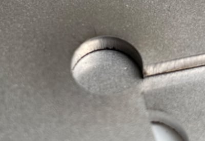
The starting point must be drawn at least 3 mm outside of the entity or at the top (see image). A distance of at least 5 mm applies to sheets that are thicker than 10 mm.
When placing the starting point, note that there must be space perpendicular to the starting point for insertion. A starting point must therefore not be placed in the middle of a narrow slot.
Depending on the contour size and stability, microjoints are placed.


| Plate thickness | Hole diameter |
| 0,5 up to 3,0 mm | 1,0 mm |
| 4,0 up to 6,0 mm | 1,5 mm |
| 8,0 up to 12,0 mm | 2,0 mm |
| 15,0 up to 25,0 mm | 4,0 mm |
≤ 3 mm: 0,3 mm
> 3 mm: 0,1 x plate thickness
Corners drawn without rounding are automatically rounded as in the information above. The same applies to all contours that are cut. Since the laser always approximates angles tangentially, angles of 90° are not possible. Plates with <3mm material thickness are automatically rounded to a radius of 0.3mm (almost perpendicular to the eye). For sheets of >3mm material thickness, 0.1x material thickness is used, the rounded corner is then visible.

Incorrect drawing, Sophia® does not recognize this part.

Correct drawing. This can be identified by the black pinhead on the blue surface.

247TailorSteel engraves only for functional purposes, such as positioning or identification. The following applies to engraving on sheet metal:
Sophia® automatically recognizes engraving lines in DXG/DWG files if they are drawn in yellow, and in 3D files if they are drawn with a depth of 0.2 mm.
You can designate cutting lines in Sophia® as engraving lines.
Sophia® will display engraving lines in yellow (and cutting contours in black).
We only engrave outlines and do not fill in areas.
The closer engraving lines are to each other, the greater the chance of a smudge. The farther apart the lines are, the neater the result. Therefore, ensure that the distance between two engraving lines is at least 1.5 mm. That way, you’ll always get the best results.
Do you want to engrave text? Then use the font ‘OLF Simple Sans OC’ (single line) or ‘TC Laser Sans’ for DXF/DWG files. For STEP files, you’ll need ‘TC Laser Sans’. Want a different font? Always use an ‘army font’ and keep the minimum distance between two engraving lines in mind (see previous points).
Engraving and cutting lines must not touch each other; otherwise, we will also cut out the engraving lines.
In 3D files, holes must never be completely enclosed by engraving lines. The engraving line will then be cut out entirely. Solution (as shown on the right): Break through the enclosed engraving with a small bridge at least 0.1 mm wide. This connection between the inner and outer parts of the engraving prevents the entire engraving from being cut out.


Specify edge finishing on your part in Sophia®

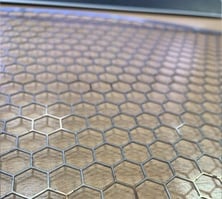
Examples of light scratches after edge finishing


Results by laser cutting with oxygen
Results by laser cutting with nitrogen
Without edge finishing
Without edge finishing
With edge finishing