Published on: 06 October 2025
Three reasons why Sophia® can’t read your 3D file
When you work with 3D files in Sophia®, you may be shown a warning that your file cannot be read properly. The result is that the manufacturability of your file cannot be adequately checked.
The following drawing errors are usually responsible:
- Overlapping curves
- Too many lines in a curve
- Missing curves
In this blog post, we explain why these errors arise and how you can easily resolve them.
Cause 1: Overlapping curves
Overlapping curves are a common drawing error. They often occur with perpendicular bends. If two ends come together in a corner, the curves overlap. This means the part cannot be manufactured.
Solution: Remove part of the bend yourself in the drawing or use a special feature in your drawing package.
We show how to find this feature in SolidWorks below.
SolidWorks
• Go to the ‘Sheet Metal’ tab.
• Select the correct side .
• Enable the ‘Trim side bends’ option.
• Click the green tick at the top.

Cause 2: Too many lines in a curve
In Sophia®, a bend profile must consist of two lines. However, if you save your drawing as a STEP file, extra lines are sometimes added to the bend profile. These lines lead to noise in Sophia® and must be removed.

Thankfully the solution is quite straightforward:
Solution: you must disable the ‘Split periodic faces’ option.
We show how to find this feature in SolidWorks, SpaceClaim, BricsCAD and MegaCAD below.
SolidWorks

- Go to 'System options'. You can find the 'Split periodic faces' option in the right column.
- Disable the 'Split periodic faces' option. The bend will profile now consist of two lines.
- Save the file again.
SpaceClaim

- Go to ‘General’.
- Now go to ‘export options’.
- Disable the 'split periodic faces' option.
- Save the drawing file again.
MegaCAD

- Go to 'File' and select 'Save' -> 'Save As'.
- Select STEP (*.STP) as the file type.
- Click 'Settings'.
- In the window that appears, go to'Export' at the top right and deselect 'Split periodic splines' option.
- Confirm the settings and save the file again.
BricsCAD
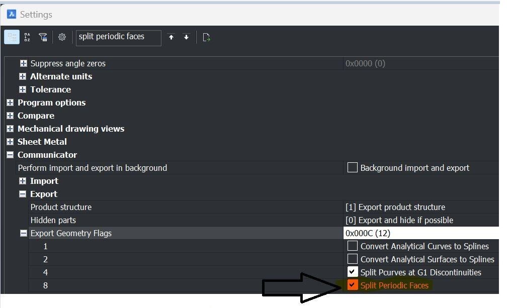
- Go to 'Settings'.
- Select 'Communicator'.
- Select 'Export Geometry Flags'.
- Deselect 'Split Periodic Faces'.
Cause 3: Missing curves
Another problem we often see is that a part has been drawn but that a curve is missing, for example. Curves are crucial if you wish to have a part made from sheet metal.
Solution: check that all curves are drawn properly or convert your drawing to ‘sheet metal’.

By converting your drawing to ‘sheet metal’, essential elements – such as missing curves – are immediately added so your drawing can be processed as sheet metal.
We show how to find this feature in SolidWorks below.
SolidWorks
• Go to the ‘Sheet Metal’ tab.
• Click ‘Convert to Sheet Metal’.
• Choose a reference plane.
• Click 'Collect all bends'. If a curve has already been drawn, click the green tick. If this is not the case, first enter the correct material thickness and choose the lines where bends must be added. Finally, click the green tick.

Do you have any questions?
Please contact our Customer Service centre. We will be happy to assist you!
/csv-import-2600x800.jpg)
/het%20verschil%20tussen%202.5D%2c%203D%20en%20XY%20Lasersnijden.jpg)
/verschillende%20soorten%20collisie%20bij%20kanten.jpg)